Open source USB dongle that decodes SAE J2716 / ISO 21097 SENT automotive sensors. Auto-learns tick period, nibble count and CRC mode. Plug-and-play virtual COM port on Windows, Linux and macOS — no proprietary drivers.
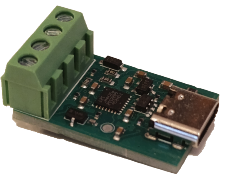
USB CDC (Virtual COM Port) adapter for SAE J2716 / ISO 21097 SENT sensors. Decodes 4-, 6- and 8-nibble frames with both DATA_ONLY and STATUS_AND_DATA CRC modes, supports CRC seeds 0x03 (SAE APR2016) and 0x05 (legacy / GM), and includes a TX mode for synthesizing SENT frames to bench-test ECUs. Talks to the host using the SLCAN text protocol over any serial terminal. SENT protocol implementation: open-sent-c.
A commercial SENT analyzer from an automotive tool vendor typically costs hundreds to thousands of euros. This one is around $23 on Tindie.
| Where | Region | Link |
|---|---|---|
| Tindie | Worldwide | https://www.tindie.com/products/lll7/sent-j2716-usb-converter/ |
| Lectronz | EU | https://lectronz.com/stores/ucandevices |
| Elty | Poland / EU | https://elty.pl/ |
| Kamami | Poland / EU | https://kamami.pl/ |
| MCU | STM32F042G4UX (UFQFPN28, 48 MHz HSI48, no crystal) |
| PA2 | SENT RX — TIM2 CH3 input capture, internal pull-up |
| PB0 | SENT TX — TIM3 CH3 output compare (toggle, AF1), DMA-driven |
| USB | Full-speed CDC (Virtual COM Port, no driver needed on Win10+) |
Sensor ──SENT signal──► PA2 (TIM2 CH3, RISING edge capture)  [RX]
                              │
                    ISR: timestamp stored in RX HAL ring buffer
                              │
                    Main loop: bridge decodes batch of 10 edges
                              │
                    SLCAN 't' frame → USB → host
- Host sends
O\r— bridge enters RX mode. - Every RISING edge on PA2 triggers the TIM2 CH3 capture ISR, which records the raw 16-bit counter value. A separate overflow ISR extends timestamps across the 16-bit rollover (~1.4 ms at 48 MHz).
SentApp_Process()(main loop) polls the RX HAL for complete batches of 10 edges: sync + status + 6 data nibbles + CRC + leading edge of next interval.- The bridge converts timestamps to µs intervals, extracts nibbles, validates CRC, and produces a CAN frame.
- The frame is serialised as
t<ID><DLC><data>\rand flushed to USB.
Default config (MLX90377): 3 µs/tick, 6 nibbles, DATA_ONLY CRC, seed 0x03, output CAN ID 0x510.
Host ──SLCAN 't' frame──► USB CDC RX callback (ISR context)
                              │
                    bridge → TX HAL (pre-expands frame into toggle array)
                    tim3_dma_start(): arm DMA and start TIM3 if idle
                              │
              TIM3 CH3 OC toggle (AF1 on PB0) fires at CCR3=1 each period:
                First toggle → pin LOW (SENT active-LOW pulse start)
                Subsequent toggles alternate LOW/HIGH per interval
              DMA1_Ch3 reloads TIM3→ARR from pre-computed buffer on each update
              Final DMA TC → TIM3 update ISR → stop timer, pin forced HIGH (idle)
- TIM3 runs at 48 MHz with no prescaler. ARR values are pre-computed (ticks × cycles_per_tick − 1) and stored in a DMA buffer. DMA1_Channel3 reloads TIM3→ARR from that buffer on every update event, so the ISR is only needed for the single end-of-frame cleanup.
- Default 1 tick = 3 µs (ARR = 143 per tick); the host can change the TX tick period at runtime (see SLCAN
SET_TX_TICKbelow). - Each SENT interval =
low_ticksactive-LOW pulse (5 ticks, SAE J2716 minimum) + rest for(N − 5)ticks. - The bridge builds the full interval sequence (sync 56T + status + nibbles + CRC + 12T pause) and the DMA drains it without any per-interval ISR involvement.
Switch to TX mode and send one frame:
O\r                       open SLCAN channel
t600102\r                 start TX mode
t52050100123456\r         transmit: status=1, nibbles [1,2,3,4,5,6]
| Command | Effect |
|---|---|
O\r |
Open — start SENT RX |
C\r |
Close — stop |
V\r / v\r |
Hardware / firmware version |
N\r |
Serial number (unique per MCU, XOR-fold of 96-bit UID) |
F\r |
Status flags |
t<ID><DLC><data>\r |
Send CAN frame |
Control frames (CAN ID 0x600):
| data[0] | DLC | Action |
|---|---|---|
01 |
1 | Start RX |
02 |
1 | Start TX |
03 |
1 | Stop |
04 |
1 | Learn tick period / nibble count / CRC mode from live signal |
05 |
3 | Set TX tick period: data[1..2] = tick_x10_us (little-endian, 0.1 µs units; valid range 20–900, i.e. 2.0–90.0 µs) |
Example — set TX tick to 5.0 µs (tick_x10_us = 50 = 0x0032):
t60030532 00\r → t6003053200\r
TX data frame (CAN ID 0x520):
t52050100123456\r
      ↑↑ ↑
      ││ └─ status byte then data nibbles packed (status=0x01, nibbles=0x00,0x12,0x34,0x56)
      │└─── DLC = 5
      └──── CAN ID 0x520
Decoded RX frame (device → host, default CAN ID 0x510):
t5103AABBCC\r DLC=3, 3 bytes = 6 nibbles packed high-nibble-first
When a slow-channel message completes, the same 0x510 frame is extended to DLC=7. The fast-channel bytes remain first, so old viewers can keep reading the angle:
byte 0..2  fast channel nibbles, unchanged for MLX90377 H.4
byte 3     slow flags: bit0=new slow message, bit1=enhanced, bit2=16-bit ESM
byte 4     slow message ID
byte 5..6  slow data, little-endian
The slow decoder supports SAE J2716 Short Serial Message and Enhanced Serial Message. MLX90377 defaults to ESM with 12-bit data and 8-bit ID. Slow-channel CRC is validated inside open-sent-c; only validated messages are forwarded.
| Script | Purpose |
|---|---|
sent_viewer.py |
General SLCAN monitor GUI with TX panel and Learn mode |
mlx_viewer.py |
MLX90377-specific GUI: angle dial + live history plot of angle & magnetic field |
sent_test.py |
CLI — open port, apply config, print received frames for N seconds |
check_rx.py |
Loopback sanity check: pings COM8 (TX), listens on COM9 (RX) |
tx_signal.py |
Continuous TX every 10 ms for logic-analyzer capture on PA4 |
verify_sent.py |
Logic2 automation: capture PA4 signal and cross-check with USB output |
pip install pyserial
verify_sent.py additionally needs pip install saleae and Logic2 running with the automation API enabled (port 10430).
A pytest suite (test_sent_integration.py) drives two SENTToUSB
dongles against each other to verify the full TX → wire → RX loop.
Hardware setup
- TX dongle on
COM15, RX dongle onCOM20(override at the top ofTestSENTIntegrationintest_sent_integration.py). - Wire PB0 of the TX dongle → PA2 of the RX dongle plus a common ground. Without that physical link the data-path tests will report "No 0x510 frames received".
Coverage (18 cases, ~60–90 s)
- Connectivity:
V/N/Fqueries, RX & TX mode entry - TX → RX frames at 4 tick periods (3, 6, 9, 12 µs)
- 10-frame back-to-back sequence
- Quiet-channel listen (no TX driver)
- Per-tick persistence across multiple frames
Each tick test first sends a 0x001 config frame to the RX device so
the bridge can derive a tick-appropriate sync_min_us threshold — the
firmware default (100 µs, calibrated for 3 µs ticks) is otherwise
fooled by long data nibbles at higher tick periods.
Run
pip install -r test_requirements.txt   # pytest>=7, pyserial>=3.5
python diagnostic.py                   # sanity-check both ports
python -m pytest test_sent_integration.py -v -s
run_tests.py provides shortcuts (all, quick, framesize,
combined, debug, single tick periods).
See TEST_INTEGRATION_README.md for the full command reference, per-test descriptions, and troubleshooting guide.
| File | Purpose |
|---|---|
test_sent_integration.py |
Main pytest suite (18 cases) |
test_requirements.txt |
Python dependencies |
TEST_INTEGRATION_README.md |
Full test documentation |
run_tests.py |
Cross-platform pytest runner with shortcuts |
diagnostic.py |
Standalone V/N/O/TX-mode probe for both ports |
STM32CubeIDE manages the Makefile. To build from the command line, set the paths to the bundled tools and run make inside the Debug folder:
set MAKE=C:\ST\STM32CubeIDE_1.19.0\STM32CubeIDE\plugins\com.st.stm32cube.ide.mcu.externaltools.make.win32_2.2.0.202409170845\tools\bin\make.exe
set GCC=C:\ST\STM32CubeIDE_1.19.0\STM32CubeIDE\plugins\com.st.stm32cube.ide.mcu.externaltools.gnu-tools-for-stm32.13.3.rel1.win32_1.0.0.202411081344\tools\bin
set PATH=%GCC%;%PATH%
cd Debug
%MAKE% -j4 all
Output: Debug/SENTToUSB.elf (~28 KB flash, ~6 KB RAM on STM32F042G4 with 32 KB flash / 6 KB SRAM).
set CLI=C:\ST\STM32CubeIDE_1.19.0\STM32CubeIDE\plugins\com.st.stm32cube.ide.mcu.externaltools.cubeprogrammer.win32_2.2.200.202503041107\tools\bin\STM32_Programmer_CLI.exe
%CLI% -c port=SWD freq=4000 -w Debug/SENTToUSB.elf -v -hardRstStep 1 — trigger DFU from the running device (replace COM8 with your port):
python -c "import serial,time; s=serial.Serial('COM8',115200,timeout=1); s.write(b'boot\r'); time.sleep(0.3); s.close()"
Step 2 — flash (~3 s after step 1, once the device enumerates as DFU):
%CLI% -c port=USB1 -w Debug/SENTToUSB.elf -v -hardRstThe boot command writes a magic value (0xDEADBEEF) to a .noinit RAM variable and resets.
On the next boot the firmware detects the magic, clears it, and jumps to the STM32F042 ROM bootloader at 0x1FFFC400.
What is SENT (SAE J2716)? SENT (Single Edge Nibble Transmission) is the SAE J2716 / ISO 21097 single-wire digital protocol used by many modern automotive sensors — pressure, position, throttle, MAP, angle — to transmit data to an ECU. Each frame is a stream of 4-bit nibbles separated by falling edges, with a status nibble, data nibbles and a CRC.
What is the cheapest USB SENT analyzer?
The uCanDevices SENT USB Converter is an open source SAE J2716 / ISO 21097 dongle around $23. It enumerates as a USB CDC virtual COM port on Windows 10+, Linux and macOS with no proprietary driver, and decodes 4-, 6- and 8-nibble SENT sensors with both DATA_ONLY and STATUS_AND_DATA CRC modes.
Can it auto-detect SENT tick period and CRC mode from an unknown sensor?
Yes. Send t600104\r to enter Learn mode. The firmware auto-detects tick period (in 0.1 µs units), nibble count (4, 6 or 8) and CRC mode, then replies once with a 0x601 result frame. Send O\r afterwards to resume RX with the learned configuration.
Can it transmit SENT frames to simulate a sensor?
Yes. Start TX mode with t600102\r, then send frame data as 0x520 CAN frames (B0 = status nibble, B1–B4 = data nibbles packed big-endian). Optional 0x600 / 05 control frame sets the TX tick period at runtime (2.0–90.0 µs). TX is driven from PB0 via TIM3 CH3 + DMA, so there is no per-interval ISR jitter.
Which sensors are known to work?
The defaults are tuned for the MLX90377 angle sensor (3 µs tick, 6 nibbles, DATA_ONLY, seed 0x03). Other verified presets include the VW/Audi 04L 906 051 L DPF sensor (~3 µs, 6 nibbles, STATUS_AND_DATA, seed 0x05) and the GM 12643955 MAP sensor (~3 µs, 6 nibbles, DATA_ONLY, seed 0x05). For other sensors, use Learn mode.
What if my sensor uses a non-standard CRC seed?
Both standard seeds are supported: 0x03 (SAE APR2016) and 0x05 (legacy / GM). Set the seed in B2 of the 0x001 configuration frame.
Is the firmware open source?
Yes — STM32F042G4 firmware in this repository, SENT protocol layer in open-sent-c. A USB DFU bootloader is included; sent_viewer.py is a free GUI client.
- SENT protocol layer: open-sent-c
- Sibling products: USB LIN Converter, USB CAN Converter (UCCB), CAN FD USB Converter (CFUC)
- Product page: https://ucandevices.github.io/sentusb.html
- All uCanDevices products: https://ucandevices.github.io/
- Contact: devices.ucan@gmail.com