This file provides useful information on how to use the feather click shield
- Got to
File > Preferencesand enterhttps://adafruit.github.io/arduino-board-index/package_adafruit_index.jsoninto the Additional Boards Manager URLs. - Click
OK. - Install
Adafruit SAMD Boardsin the Boards Manager. - Click
Tools > Board > Adafruit SAMD Boardsand selecte theAdafruit Feather M4 CAN.
See https://learn.adafruit.com/adafruit-feather-m4-can-express/arduino-ide-setup for more information.
- Place your
Adafruit feather M4 CANin the center of theFeather click shield. - Place your
Click Boardsinto themikroBUSsockets. - Connect a USB-C cable into to your computer and directly to the
Feather M4 CAN(the upper USB-C port).
This section provides useful links, images and code snippets for every component and click board.
Pinout of the feather click shield:
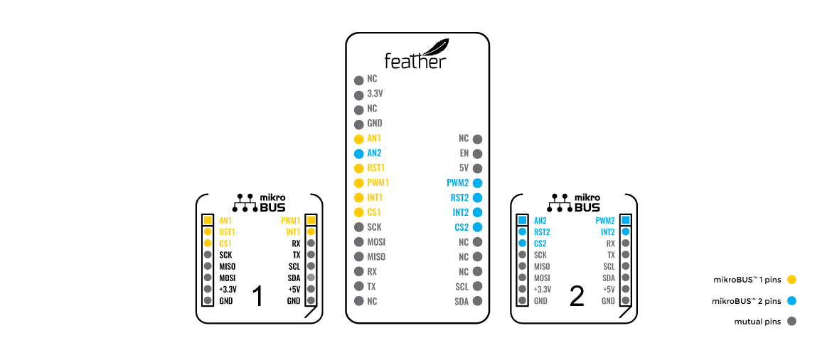
Pinout of the adafruit feather m4 can:
Component description: https://www.mikroe.com/touchpad-4-click
Controller datasheet: https://www.azoteq.com/images/stories/pdf/iqs7211a_datasheet.pdf
Code example (not perfect):
#include <Wire.h>

#define ADDR 0x56
#define INT_PIN 11 // for microBUS 1
// #define INT_PIN 18 // for microBUS 2

#define LEFT 0
#define RIGHT 1
#define DOWN 2
#define UP 3
#define SINGLE_TAP 4
#define PRESS_AND_HOLD 5

#define GESTURE_READ_FAILED 999

#define ADDR_INFO_FLAGS 0x10
#define ADDR_GESTURES 0x11
#define ADDR_FINGER_X 0x14
#define ADDR_FINGER_Y 0x15
#define ADDR_TOUCH_STRENGTH 0x16
#define ADDR_FINGER_AREA 0x17

volatile bool gestureRegistered = false;

int readRegister(int addr)
{
  int data = 0;

  Wire.beginTransmission(ADDR);
  Wire.write(addr); // Gestures register
  Wire.endTransmission(0);

  // Read gestures
  Wire.requestFrom(ADDR, 2);
  if (Wire.available() >= 2) {
    byte byte1 = Wire.read();
    byte byte2 = Wire.read();

    data = (byte2 << 8) | byte1;
  }
  return data;
}

int readGestures()
{
  int data = readRegister(ADDR_GESTURES);

  if (data & 1) return SINGLE_TAP;
  if (data & 2) return PRESS_AND_HOLD;
  if (data & 4) return RIGHT;
  if (data & 8) return LEFT;
  if (data & 16) return DOWN;
  if (data & 32) return UP;
  return GESTURE_READ_FAILED;
}

int readTouchStrength()
{
  int data = readRegister(ADDR_TOUCH_STRENGTH);
  return data;
}

int readFingerX()
{
  int data = readRegister(ADDR_FINGER_X);
  return data;
}

int readFingerY()
{
  int data = readRegister(ADDR_FINGER_Y);
  return data;
}

void ISR()
{
  gestureRegistered = true;
}

void setup()
{
  Serial.begin(9600);

  pinMode(INT_PIN, INPUT);
  attachInterrupt(digitalPinToInterrupt(INT_PIN), ISR, FALLING);
  Wire.begin();

  // Config
  Wire.beginTransmission(ADDR);
  Wire.write(0x51);
  Wire.write(0x4710);
  Wire.endTransmission();
}

void loop()
{
  if (gestureRegistered)
  {
    int gesture = readGestures();

    switch (gesture)
    {
      case LEFT:
        Serial.println("Left");
        break;
      case RIGHT:
        Serial.println("Right");
        break;
      case UP:
        Serial.println("Up");
        break;
      case DOWN:
        Serial.println("Down");
        break;
      case SINGLE_TAP:
        Serial.println("Single tap");
        break;
      case PRESS_AND_HOLD:
        Serial.println("Press and hold");
        break;
      default:
        break;
    }

    gestureRegistered = false;
  }
}Component description: https://www.mikroe.com/oled-c-click
Graphics driver datasheet: https://newhavendisplay.com/content/app_notes/SSD1351.pdf
Library: https://github.com/adafruit/Adafruit-SSD1351-library (Can be found in Library Manager. Search: Adafruit SSD1351)
NOTE: This library doesn't support the 96x96 OLED display. Everything will be offset. No better library was found.
Code example (draw different shapes):
#include <Adafruit_GFX.h>
#include <Adafruit_SSD1351.h>
#include <SPI.h>


// Definitions for display offsets. Always set pixels only within this range, otherwise they will be off-screen. (This is because the available library doesn't support our resolution)
#define MIN_X  16
#define MIN_Y 0
#define MAX_X  111
#define MAX_Y 95

// Using Microbus 1
#define SCLK_PIN 25
#define MOSI_PIN 24
#define DC_PIN   17
#define CS_PIN   19
#define RST_PIN  16
#define EN_PIN   18

// // Using Microbus 2
// #define SCLK_PIN 25
// #define MOSI_PIN 24
// #define DC_PIN   13
// #define CS_PIN   10
// #define RST_PIN  12
// #define EN_PIN   11

// Color definitions
#define	BLACK           0x0000
#define WHITE           0xFFFF
#define	BLUE            0xF800
#define	RED             0x001F
#define	GREEN           0x07E0
#define YELLOW          0x07FA
#define PURPLE          0xF81F

Adafruit_SSD1351 tft = Adafruit_SSD1351(128, 128, CS_PIN, DC_PIN, MOSI_PIN, SCLK_PIN, RST_PIN);

void testOLED()
{
  // Single pixels
  tft.fillScreen(BLACK);
  for(int i = MIN_X; i <= MAX_X; i++)
  {
    for (int j = MIN_Y; j <= MAX_Y; j++)
    {
      tft.drawPixel(i, j, WHITE);
      delay(1);
    }
  }

  tft.fillScreen(BLACK);

  // line
  tft.drawLine(MIN_X, MIN_Y, MAX_X, MAX_Y, WHITE);
  delay(3000);

  tft.fillScreen(BLACK);

  // rectangle
  tft.drawRect(50, 50, 20, 20, YELLOW);
  delay(3000);
  // fill it
  tft.fillRect(50, 50, 20, 20, YELLOW);
  delay(3000);

  // circle
  tft.drawCircle(40, 40, 15, BLUE);
  delay(3000);
  // fill it
  tft.fillCircle(40, 40, 15, BLUE);
  delay(3000);

  tft.fillScreen(BLACK);
}


void setup(void) {
  Serial.begin(9600);

  // Set enable pin to high
  pinMode(EN_PIN, OUTPUT);
  digitalWrite(EN_PIN, HIGH);

  tft.begin();
}

void loop() {
  testOLED();
}Component description: https://www.mikroe.com/smart-mic-click
Acoustic processor datasheet: http://download.mikroe.com/documents/datasheets/IA611_datasheet.pdf
Component description: https://www.mikroe.com/thumbstick-click
Datasheet zum A/D-Converter: http://ww1.microchip.com/downloads/en/devicedoc/21298e.pdf
Thumbstick Layout:
Code example (read thumbstick and button input):
#include <SPI.h>

// For microBUS 1
#define CS_PIN 19
#define THUMBSTICK_BUTTON_PIN 18

// // For microBUS 2
// #define CS_PIN 10
// #define THUMBSTICK_BUTTON_PIN 11

#define DEBOUNCE_TIME_MS 10

volatile unsigned long lastButtonPress = 0;

int read_thumbstick(int channel) {
  int value = 0;

  // Select the MCP3204
  digitalWrite(CS_PIN, LOW);

  // Send the start bit, single-ended mode, and channel selection bits
  byte command = B11000000 | (channel << 3);
  SPI.transfer(command);

  // Read the 12-bit result (MSB first)
  value = SPI.transfer(0) & B00001111;
  value = (value << 8) + SPI.transfer(0);

  // Deselect the MCP3204
  digitalWrite(CS_PIN, HIGH);

  return value;
}

void get_user_input()
{
  int dir = 0;

  // Read value for both axes
  int value_0 = read_thumbstick(0);
  int value_1 = read_thumbstick(1);

  int vert = 0;
  int hor = 0;

  // Use thresholds to convert input into (binary) directions
  // This is not required but was used to counter noisy input.
  if (value_0 > 3500) vert = -1;
  else if (value_0 < 500) vert = 1;
  else vert = 0;

  if (value_1 > 3500) hor = 1;
  else if (value_1 < 500) hor = -1;
  else hor = 0;

  Serial.print("User input: vert: ");
  Serial.print(vert);
  Serial.print("  hor: ");
  Serial.print(hor);
  Serial.println();
}

void onThumbstickPressed()
{
  // Debouncing
  unsigned long now = millis();
  if ((now - lastButtonPress) < DEBOUNCE_TIME_MS) return;

  Serial.println("Pressed thumbstick");

  lastButtonPress = now;
}

void setup()
{
  Serial.begin(9600);

  SPI.begin();

  pinMode(CS_PIN, OUTPUT);
  pinMode(THUMBSTICK_BUTTON_PIN, INPUT_PULLUP);
  attachInterrupt(digitalPinToInterrupt(THUMBSTICK_BUTTON_PIN), onThumbstickPressed, FALLING);
}

void loop()
{
  get_user_input();
  delay(100);
}Component description: https://www.mikroe.com/8800-retro-click
LED driver datasheet: https://ams.com/documents/20143/36005/AS1115_DS000206_1-00.pdf
Code example (flash the character '!' on and off):
#include <Wire.h>

byte characterOne[] = {0,0,0,1,1,0,0,0,
                       0,0,0,1,1,0,0,0,
                       0,0,0,1,1,0,0,0,
                       0,0,0,1,1,0,0,0,
                       0,0,0,1,1,0,0,0,
                       0,0,0,0,0,0,0,0,
                       0,0,0,1,1,0,0,0,
                       0,0,0,1,1,0,0,0};

 byte characterTwo[] = {0,0,0,0,0,0,0,0,
                        0,0,0,0,0,0,0,0,
                        0,0,0,0,0,0,0,0,
                        0,0,0,0,0,0,0,0,
                        0,0,0,0,0,0,0,0,
                        0,0,0,0,0,0,0,0,
                        0,0,0,0,0,0,0,0,
                        0,0,0,0,0,0,0,0};

byte i2c_addr = 0x00;

// Write to 8x8 LED matrix
void show(byte data[]) {
  for (int x=0; x < 8; x++) {
    byte line = 0;
    for (int y=0;y < 8; y++) {
        line = line << 1;
        line = line | data[x*8+y];
    }
    Wire.beginTransmission(i2c_addr);
    Wire.write(x+1);  // select segment
    Wire.write(line); // select digit
    Wire.endTransmission();
  }
}


void setup()
{
  Serial.begin(9600);

  // LED matrix
  Wire.begin(); // join i2c bus (address optional for master)

  // Wakeup from shutdown mode
  Wire.beginTransmission(i2c_addr);
  Wire.write(0x0c);
  Wire.write(0x81);
  Wire.endTransmission();
  delay(1);

  // This device can change slave address dynamically.
  // see p.15 more detail

  // Change device address (p.15)
  Wire.beginTransmission(i2c_addr);
  Wire.write(0x2d); // register
  Wire.write(0x01); // user-defined (0x03 if not connected any pins)
  Wire.endTransmission();
  delay(1);

  i2c_addr = 0x03; // address changed from here

  // Intensity control (0x0A)
  Wire.beginTransmission(i2c_addr);
  Wire.write(0x0a); // register
  //Wire.write(0x0f); // 15/16 (max)
  Wire.write(0x07); // 8/16 (median)
  //Wire.write(0x00); // 1/16 (min)
  Wire.endTransmission();
  delay(1);

  // Scan-Limit Register (0x0B)
  Wire.beginTransmission(i2c_addr);
  Wire.write(0x0b);
  Wire.write(0x07); // display all digits 0:7
  Wire.endTransmission();
  delay(1);

  // Non-decode mode (0x09) for 8x8 dot matrix
  Wire.beginTransmission(i2c_addr);
  Wire.write(0x09);
  Wire.write(0x00); // non-decode mode
  Wire.endTransmission();
  delay(1);
}

void loop()
{
  show(characterOne);
  delay(400);
  show(characterTwo);
  delay(400);
}Component description: https://www.mikroe.com/10x10-rgb-click
LED library (can be directly installed in ArduinoIDE or PlatformIO): https://github.com/adafruit/Adafruit_NeoPixel
Code example:
#include <Adafruit_NeoPixel.h>

#define PIN 17 // For microBUS 1
// #define PIN 13 // For microBUS 2
#define NUM_PIXELS 100

Adafruit_NeoPixel LEDs(NUM_PIXELS, PIN, NEO_GRB + NEO_KHZ800);

void setup() {
  // Start LEDs
  LEDs.begin();

  // Clear all LEDs
  LEDs.clear();

  // Set brightness of all LEDs. [0, 255]
  LEDs.setBrightness(40);
}

void loop() {
  for(int i=0; i<NUM_PIXELS; i++) {
    // Set color of individual LED
    LEDs.setPixelColor(i, LEDs.Color(255-(2*i), 150, i*2));
    // Write to hardware, else nothing would show
    LEDs.show();
    delay(20);
  }
  for(int i=0; i<NUM_PIXELS; i++) {
    // Set color of individual LED
    LEDs.setPixelColor(i, LEDs.Color(0, 0, 0));
    // Write to hardware, else nothing would show
    LEDs.show();
    delay(20);
  }
}Component description: https://www.mikroe.com/mpu-9dof-click
Datasheet: https://invensense.tdk.com/wp-content/uploads/2015/02/PS-MPU-9250A-01-v1.1.pdf
Library and examples: https://github.com/hideakitai/MPU9250
Code example (get roll, pitch and yaw):
#include "MPU9250.h"

MPU9250 mpu;

void setup() {
    Serial.begin(9600);
    Wire.begin();
    mpu.setup(0x68);
}

void loop() {
  if (mpu.update()) {
    print_roll_pitch_yaw();
  }
}

void print_roll_pitch_yaw() {
    Serial.print("Yaw, Pitch, Roll: ");
    Serial.print(mpu.getYaw(), 2);
    Serial.print(", ");
    Serial.print(mpu.getPitch(), 2);
    Serial.print(", ");
    Serial.println(mpu.getRoll(), 2);
}Component description: https://www.mikroe.com/proximity-18-click
Datasheet: https://download.mikroe.com/documents/datasheets/VCNL3036X01_datasheet.pdf
Install library: https://github.com/JenertsA/VCNL3040_Proximity_Sensor_Library (Available in Library Manager of Arduino Ide. Search: VCNL3040) NOTE: Go to VCNL3040.h and change VCNL3040_DEV_ADDRESS from 0x60 to 0x41.
Code example (read proximity value):
#include <VCNL3040.h>
#include <Wire.h>

VCNL3040 sens;

void setup()
{
  Serial.begin(9600);
  Wire.begin();
  sens.begin();
  sens.startReading();
}

void loop()
{
  unsigned int dist_raw = sens.readPSData();
  Serial.println(dist_raw);
  delay(100);
}Component description: https://www.mikroe.com/radar-click
Datasheet: https://download.mikroe.com/documents/datasheets/MM5D91-00_datasheet.pdf
Libraries for click boards by MIKROE (NOT compatible with our board but can be useful): https://github.com/MikroElektronika/mikrosdk_click_v2
Run this code snipped to get the i2c addresses of the connected devices:
#include <Wire.h>


void setup()
{
  Wire.begin();

  Serial.begin(9600);
  while (!Serial);             // Leonardo: wait for serial monitor
  Serial.println("\nI2C Scanner");
}


void loop()
{
  byte error, address;
  int nDevices;

  Serial.println("Scanning...");

  nDevices = 0;
  for(address = 1; address < 127; address++ )
  {
    // The i2c_scanner uses the return value of
    // the Write.endTransmisstion to see if
    // a device did acknowledge to the address.
    Wire.beginTransmission(address);
    error = Wire.endTransmission();

    if (error == 0)
    {
      Serial.print("I2C device found at address 0x");
      if (address<16)
        Serial.print("0");
      Serial.print(address,HEX);
      Serial.println("  !");

      nDevices++;
    }
    else if (error==4)
    {
      Serial.print("Unknown error at address 0x");
      if (address<16)
        Serial.print("0");
      Serial.println(address,HEX);
    }
  }
  if (nDevices == 0)
    Serial.println("No I2C devices found\n");
  else
    Serial.println("done\n");

  delay(5000);           // wait 5 seconds for next scan
}