A PCB for controlling the motors in a go baby go car with joystick control
Questions? Please email our support line at gbg-pcb@googlegroups.com
https://github.com/gobabygocarswithjoysticks/gbg-pcb

V2.1
This board replaces the control box of a car's original electronics or the separate ESCs and Arduino in the usual joystick go baby go modification. The board has screw terminals for connecting to the battery, motors, and the joystick. With this circuit board, a car can be converted to joystick control without any soldering.
- V2 GBG-PCBs can run from 6 to 24 volt batteries.
- V2 boards can also be configured with battery, motor, and signal plugs that match the plugs on the common weelye control boxes. This means some cars can be converted to joystick control without cutting any wires.
- Version 2 boards can supply approximately 5 amps per motor continuously.
- For the previous versions of the GBG-PCB see https://github.com/gobabygocarswithjoysticks/gbg-pcb/tree/version_1
- Version 1 GBG-PCBs had a higher, 10 amp current capacity and a lower part count but only runs on 12 volts.
Here's a few options:
- Please feel free to use these files and get boards yourself. There are instructions here for how to make GBG-PCBs by hand.
- Use this PCBWay link to order fully assembled boards. Or, alternative PCBWay links if you want to complete the assembly yourself: PCBWay can do everything but leave the battery, motor, and button connectors off or, PCBWay can do the challenging surface mount soldering and leave the through-hole soldering for you
- Email gobabygocarswithjoysticks@gmail.com. We may have a spare V1 or V2 GBG-PCB that we can donate to you.
- Email pnwassistivetech@gmail.com or visit the PNW Assistive Technology website. Thank you to PNWAT for sponsoring V2 GBG-PCB prototyping runs and being a supplier of V1 and V2 GBG-PCBs (called "plug and drive boards" by PNWAT).
The website for uploading software to a GBG-PCB and adjusting settings is here: https://gobabygocarswithjoysticks.github.io/programmer/
- Aosom Jeep - old model (car is out of production)
- Zupapa Bumper Car (instructions are complete through electronics but don't include a backrest or joystick holder)
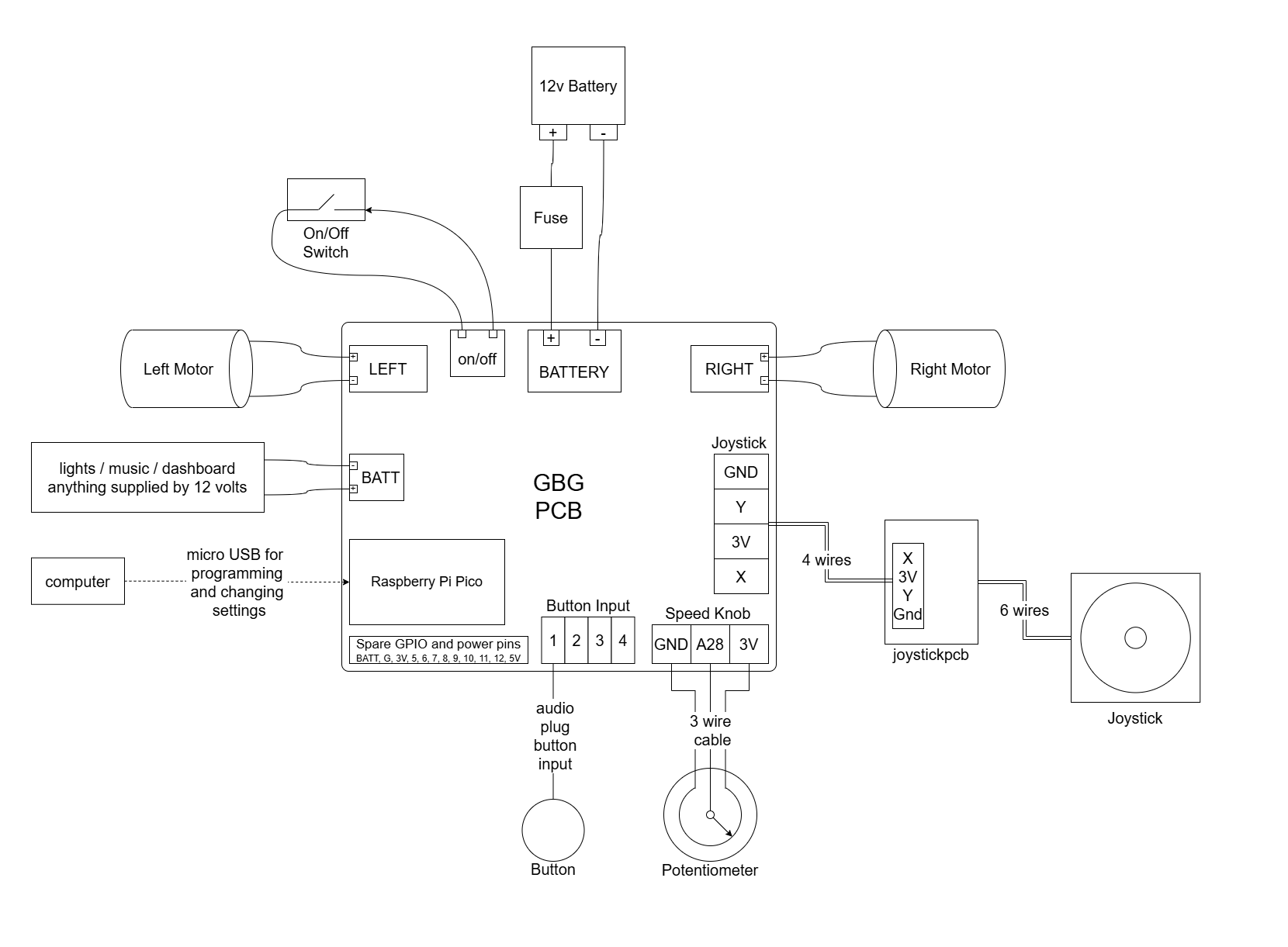
See the above link for notes on how to add cooling fans to the case to increase the current capacity.
Use KiCAD 10.0
Run this github action when you push changes to the KiCAD files. The action updates the images of the CAD, the gerber files, the schematic, and other PCB production files.


