


Raspberry Pi kernel driver for Onsemi AR0234, a 2.3 MP global shutter 1/2.6" CMOS sensor.
- 2-lane and 4-lane MIPI CSI-2 (up to 900 Mbps/lane)
- 8-bit and 10-bit RAW output
- 1920×1200 @ 120 fps (full resolution)
- 960×600 @ 237 fps (2×2 binning)
- External trigger modes (pulsed, automatic, sync-sink)
- Flash output with programmable lead/lag delay
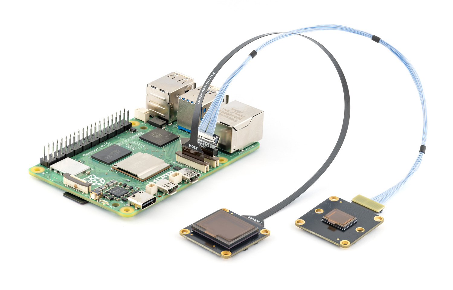
AR0234 camera modules are available at kurokesu.com
Connect camera to CSI port with Pi powered off.
Update OS and reboot:
sudo apt update && sudo apt full-upgrade -y
sudo reboot
Important
If driver or camera stack was previously built from source, run one-time cleanup before first apt install. See migrating from a source install.
Enable Kurokesu apt archive (skip if already enabled):
curl -fsSLO https://apt.kurokesu.com/setup.sh
sudo sh setup.sh
Install driver and camera stack:
sudo apt update
sudo apt install -y ar0234-rpi-dkms rpicam-apps
With archive enabled, apt resolves Kurokesu rpicam-apps and libcamera forks with AR0234 support as updates to stock packages. Later updates arrive with regular apt upgrade.
Edit boot configuration:
sudo nano /boot/firmware/config.txtMake two changes:
- Find
camera_auto_detectnear the top and set it to0:
camera_auto_detect=0- Add
dtoverlay=ar0234under the[all]section at the bottom of the file:
[all]
dtoverlay=ar0234
If camera is connected to cam0 port, use dtoverlay=ar0234,cam0 instead. See cam0.
Save and exit.
config.txt changes take effect after reboot:
sudo rebootVerify camera is detected:
rpicam-hello --list-camerasExpected output (varies by link frequency and lane configuration):
Available cameras
-----------------
0 : ar0234 [1920x1200 10-bit GRBG] (/base/axi/pcie@1000120000/rp1/i2c@80000/ar0234@10)
    Modes: 'SGRBG10_CSI2P' : 960x600 [236.85 fps - (0, 0)/1920x1200 crop]
                             1280x720 [198.49 fps - (320, 240)/1280x720 crop]
                             1920x1080 [133.58 fps - (60, 0)/1920x1080 crop]
                             1920x1200 [120.45 fps - (0, 0)/1920x1200 crop]
Start live preview:
rpicam-hello -t 0On headless systems, capture a still image instead:
rpicam-still -o test.jpgar0234 overlay supports comma-separated options to override defaults:
| option | description | default |
|---|---|---|
cam0 |
Use cam0 port instead of cam1 | cam1 |
4lane |
Use 4-lane MIPI CSI-2 (if wired) | 2 lanes |
link-frequency=<Hz> |
Set MIPI CSI-2 link frequency (Hz) | 450000000 |
external-trigger |
Pulse/automatic trigger mode via TRIG pin | off |
sync-sink |
Multi-sensor sync mode (frame timing locked to TRIG pin) | off |
always-on |
Keep regulator powered (prevents runtime PM power-off) | off |
flash |
Enable FLASH output pin (HIGH during exposure) | off |
flash-lead=<n> |
Flash lead delay (~3.4 µs/unit 4-lane, ~6.8 µs/unit 2-lane) | 0 |
flash-lag=<n> |
Flash lag delay (~3.4 µs/unit 4-lane, ~6.8 µs/unit 2-lane) | 0 |
If camera is connected to cam0 port, append ,cam0:
dtoverlay=ar0234,cam0To enable 4-lane MIPI CSI-2, append ,4lane:
dtoverlay=ar0234,4laneWarning
Before using 4lane, confirm your camera port actually supports 4-lane MIPI CSI. Not all Raspberry Pi models and carrier boards provide 4-lane MIPI CSI on both ports.
Supported link frequencies: 450 MHz (default, 10-bit only) and 360 MHz (8-bit only). Sensor PLL constraints tie bit depth to link frequency, switch to 360 MHz if you need 8-bit output.
To set link frequency to 360 MHz, append ,link-frequency=360000000:
dtoverlay=ar0234,link-frequency=360000000| Link frequency | Data rate / lane | Lanes | Bit depth | Width | Height | Max FPS |
|---|---|---|---|---|---|---|
| 960×600 (2×2 binned) | ||||||
| 360 MHz | 720 Mbps | 2 | 8 | 960 | 600 | 119 fps |
| 450 MHz | 900 Mbps | 2 | 10 | 960 | 600 | 119 fps |
| 360 MHz | 720 Mbps | 4 | 8 | 960 | 600 | 237 fps |
| 450 MHz | 900 Mbps | 4 | 10 | 960 | 600 | 237 fps |
| HD 720p (sensor crop) | ||||||
| 360 MHz | 720 Mbps | 2 | 8 | 1280 | 720 | 100 fps |
| 450 MHz | 900 Mbps | 2 | 10 | 1280 | 720 | 100 fps |
| 360 MHz | 720 Mbps | 4 | 8 | 1280 | 720 | 200 fps |
| 450 MHz | 900 Mbps | 4 | 10 | 1280 | 720 | 200 fps |
| Full HD 1080p (sensor crop) | ||||||
| 360 MHz | 720 Mbps | 2 | 8 | 1920 | 1080 | 67 fps |
| 450 MHz | 900 Mbps | 2 | 10 | 1920 | 1080 | 67 fps |
| 360 MHz | 720 Mbps | 4 | 8 | 1920 | 1080 | 134 fps |
| 450 MHz | 900 Mbps | 4 | 10 | 1920 | 1080 | 134 fps |
| 1920×1200 (full resolution) | ||||||
| 360 MHz | 720 Mbps | 2 | 8 | 1920 | 1200 | 60 fps |
| 450 MHz | 900 Mbps | 2 | 10 | 1920 | 1200 | 60 fps |
| 360 MHz | 720 Mbps | 4 | 8 | 1920 | 1200 | 120 fps |
| 450 MHz | 900 Mbps | 4 | 10 | 1920 | 1200 | 120 fps |
Note
These framerates do not apply to pulsed trigger mode. See external-trigger.
Tip
Options can be combined. Example (cam0, 4-lane, 360 MHz):
dtoverlay=ar0234,cam0,4lane,link-frequency=360000000AR0234 supports two external trigger modes. Both use TRIG pin on camera module as external signal input. TRIG is a 1.8V logic level input wired directly to sensor. Trigger pulse only initiates capture, exposure time remains controlled by sensor's integration time register.
TRIG and FLASH signals are available on AUX connector:
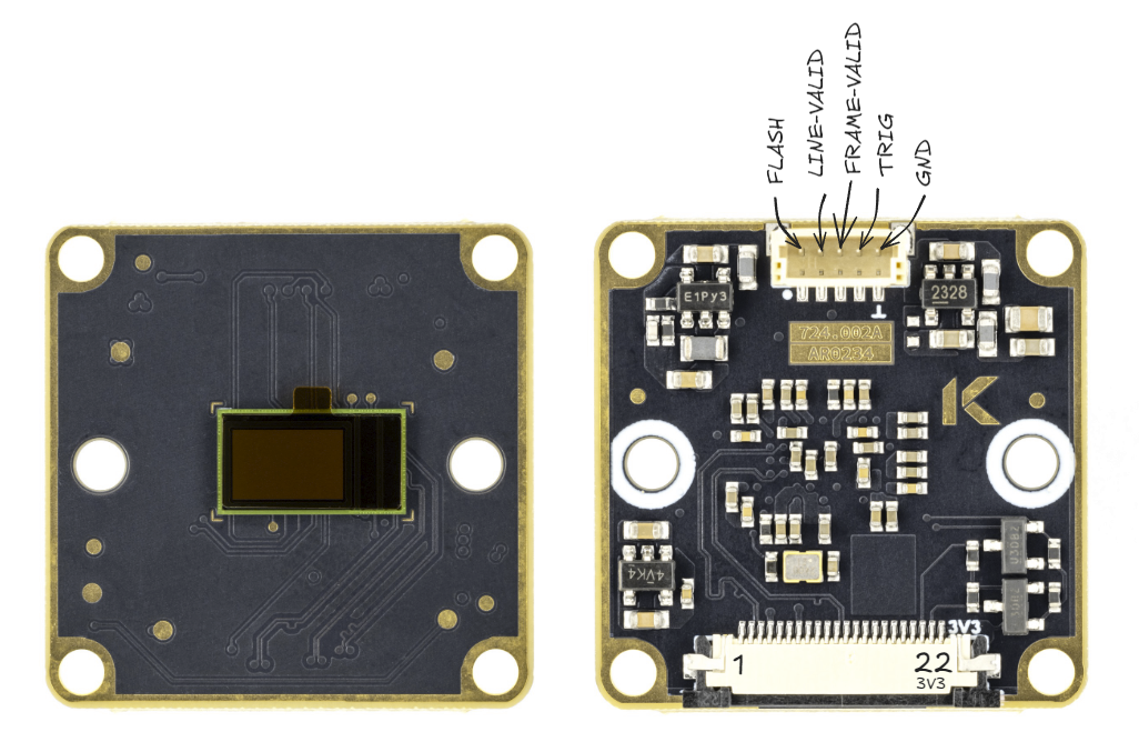
Full module pinout and AUX connector part number are documented in 234x-CSI wiki page
Sensor stays in standby and waits for activity on TRIG pin. Exposure and readout happen sequentially: readout does not begin until exposure is complete. Two sub-modes are available:
- Pulsed: each high pulse on
TRIGpin captures a single frame (minimum pulse width 125 ns, 3 EXTCLK cycles at 24 MHz). Framerate is determined by pulse frequency. - Automatic: if
TRIGsignal stays high, sensor outputs frames continuously at configured framerate.
dtoverlay=ar0234,external-triggerWhen using rpicam-apps in pulsed trigger mode, start with a fixed shutter duration and gain:
rpicam-hello -t 0 --qt-preview --shutter 10000 --gain 2.0Important
Always specify a fixed shutter duration and gain, to ensure the AGC does not try to adjust them automatically. With external trigger the AGC tends to go unstable.
Shutter value directly controls sensor exposure time and must satisfy:
exposure_time < trigger_period - (1 / max_fps) - ~1.6 ms
Where max_fps is maximum framerate for your mode from output formats table, and ~1.6 ms accounts for MIPI wakeup and internal sensor overhead. For example, at full resolution 4-lane 10-bit (max 120 fps) triggered at 30 Hz: 1/30 - 1/120 - 1.6 ms ≈ 23.7 ms maximum exposure time.
Maximum trigger frequency for pulsed mode:
| Resolution | Lanes | Max trigger frequency |
|---|---|---|
| 1920×1200 (full resolution) | 2 | 30 Hz |
| 4 | 60 Hz | |
| 960×600 (2×2 binned) | 2 | 60 Hz |
| 4 | 120 Hz |
Sensor streams continuously but locks frame timing to external TRIG signal. Unlike external-trigger, exposure and readout overlap (pipelined), so higher framerates are possible. Trigger period must not be shorter than configured frame length.
dtoverlay=ar0234,sync-sinkTrigger modes can also be set at runtime via module parameter:
# 0=off, 1=external-trigger, 2=sync-sink
echo 1 | sudo tee /sys/module/ar0234/parameters/trigger_mode
Note
Module parameter is global: in a multi-camera setup it applies to all AR0234 sensors. To configure each sensor independently, use device tree overlay options instead. Device tree setting takes precedence over module parameter.
always-on keeps camera regulator permanently enabled, preventing kernel from powering off sensor during runtime PM suspend.
dtoverlay=ar0234,always-onAR0234 has a FLASH output pin (1.8V logic level) that goes HIGH during sensor exposure, useful for synchronizing external illumination such as strobes or LEDs.
To enable flash output:
dtoverlay=ar0234,flashBy default, flash pulse closely follows exposure period (longer by ~8 µs on 4-lane or ~16 µs on 2-lane due to sensor overhead). The flash signal start can be shifted relative to exposure using flash-lead or flash-lag:
flash-lead: flash starts before exposure, extending total flash timeflash-lag: flash starts after exposure begins, shortening total flash time
Both accept values in the range 0 to 127, where each unit is approximately 3.4 µs (4-lane) or 6.8 µs (2-lane).
# Flash starts ~34 µs before exposure (4-lane)
dtoverlay=ar0234,4lane,flash,flash-lead=10

# Flash starts ~34 µs after exposure begins (4-lane)
dtoverlay=ar0234,4lane,flash,flash-lag=10
For most use cases, small delay values (single digits) are sufficient. Large delay values combined with short exposure times are not recommended. For short exposures (below ~450 µs on 4-lane or ~900 µs on 2-lane), flash-lead should not be used.
Note
In trigger mode, flash output is suppressed when the trigger pulse is shorter than ~1.5 ms.
Install required tools:
sudo apt install -y git
sudo apt install -y --no-install-recommends dkms
Clone this repository:
cd ~
git clone https://github.com/Kurokesu/ar0234-rpi-driver.git
cd ar0234-rpi-driver/
If driver was installed from apt archive previously, remove it first:
sudo apt remove ar0234-rpi-dkmsRun setup script:
sudo ./setup.shCamera stack, boot configuration and verification follow Install. Skip ar0234-rpi-dkms there, only rpicam-apps is needed. To build libcamera and rpicam-apps from source as well, see libcamera/BUILDING.md.
One-time cleanup before first apt install.
Remove ar0234 driver modules installed by setup.sh:
dkms status | grep ar0234 | cut -d, -f1 | sort -u | xargs -rI{} sudo dkms remove {} --allSource-built libcamera and rpicam-apps install to /usr/local and shadow packaged binaries. Remove them:
Warning
Command below deletes everything under /usr/local with libcamera, rpicam or libpisp in its name, including custom scripts or files named after them.
sudo find /usr/local -depth \( -name '*libcamera*' -o -name '*rpicam*' -o -name '*libpisp*' \) -exec rm -rf {} +Cleanup complete. Continue with install steps.
- 6by9 for sharing modded ar0234 driver and libcamera code.
- Will Whang for imx585-v4l2-driver, used as basis for structuring this driver.