Hello!
I tried the code tsl1401_new.ino and it seems that it only read the first 64 pixels properly.
The sensor is a tsl1401R and I use an arduino nano to read it.
I modified the code a bit to print the raw values. I noticed that the first 64 pixels are normal: if I cover the sensor, the values decrease. But pixel values of 65-128 are always low (0-10) - it seems like static noise.
I also have two tsl1401R ICs, both showing the same thing.
What’s extra strange is that this 64-pixel value covers the full width of the sensor. So I move a thin cover over the sensor from one side to the other, it travels nicely from 0 to 64 pixels. So pixel 0 is one edge of the sensor, while pixel 64 is the other edge ... Strange.
I've tried 3-4 possible codes for this IC, and the same is true with any of them, so I don't think there is a problem with the code. Anyway, this is the best written code, very easy to follow, and it works best as well as the fastest. Thanks for :)
I've found a visualizer code for Processing - originally written for TSL201R (it's a similar 64 pixel chip) - and I've modified it to display 128 pixel.
As You can see in the picture: (the low values are a pencil's tip above the middle of the sensor)
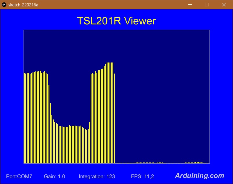
So I don’t know where the chips are, I got them from a colleague to experiment with. After a lot of trying, I came to the conclusion that these could not be 128 pixel chips. Maybe a fake 64-pixel sensor stamped with 1401, or something ... Could it be like that?
But if it's a real 128 pixel sensor, what can be the problem? How can I read the 128 values?
Hello!
I tried the code tsl1401_new.ino and it seems that it only read the first 64 pixels properly.
The sensor is a tsl1401R and I use an arduino nano to read it.
I modified the code a bit to print the raw values. I noticed that the first 64 pixels are normal: if I cover the sensor, the values decrease. But pixel values of 65-128 are always low (0-10) - it seems like static noise.
I also have two tsl1401R ICs, both showing the same thing.
What’s extra strange is that this 64-pixel value covers the full width of the sensor. So I move a thin cover over the sensor from one side to the other, it travels nicely from 0 to 64 pixels. So pixel 0 is one edge of the sensor, while pixel 64 is the other edge ... Strange.
I've tried 3-4 possible codes for this IC, and the same is true with any of them, so I don't think there is a problem with the code. Anyway, this is the best written code, very easy to follow, and it works best as well as the fastest. Thanks for :)
I've found a visualizer code for Processing - originally written for TSL201R (it's a similar 64 pixel chip) - and I've modified it to display 128 pixel.

As You can see in the picture: (the low values are a pencil's tip above the middle of the sensor)
So I don’t know where the chips are, I got them from a colleague to experiment with. After a lot of trying, I came to the conclusion that these could not be 128 pixel chips. Maybe a fake 64-pixel sensor stamped with 1401, or something ... Could it be like that?
But if it's a real 128 pixel sensor, what can be the problem? How can I read the 128 values?